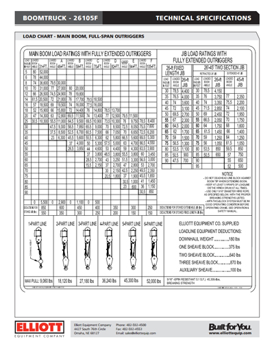
Using the Elliott 26105F Boom Truck technical specification sheet as a reference, this article will walk you through the method of reading a load chart. There are two charts that make up a spec sheet. For all charts, if work is being performed at a boom length not defined on the load chart, the operator must use the load/capacity rating at the next longest defined boom length on the chart for a given radius.
The first is the Load Ratings Chart, which provides the crane capacities at certain boom angles and radius. The second is the Range Diagram, which provides a snapshot of the boom position when looking at height, radius, and boom angle.
Load Ratings: The rated capacities of the main boom are shown in the chart on the left side titled “Main Boom Load Ratings with Fully Extended Outriggers”. The top row represents the boom length. The left column represents the operating radius. The rated crane capacity and boom angle align with a specific boom length and operating radius. For example, at a 31-ft. boom length and 16-ft. radius, the 26105F has a rated capacity of 18,500 lb. at a 57 degree boom angle. The right side of the chart has the same setup, but shows the rated capacities with the optional jibs. For the 26105, there are two jibs, a 26’ fixed jib or a 26-45’ two-piece jib.
The bold line on the chart represents the separation of structural strength and stability. Any capacities below the bold line are limited by the crane’s stability. Any capacities above the bold line are limited by the structural strength of the crane. For the 26105, there are no stability limits, since no capacities are shown below the bold line on the chart.
Deductions also have to be figured into the crane capacities. A list of possible deductions is shown at the bottom of the main boom chart and the bottom right of the entire chart. This includes deductions for when the jib is stowed on the boom, for downhaul weights, and for multi-part line blocks.
The lower left section of the chart illustrates the parts of line required to reach each capacity. The crane load line will have to be multi-parted accordingly, depending upon the capacity that needs to be lifted. For example, the 26105 load line has a capacity of 9,060 lb. A lift of 15,000 lb. would require a two-part line, which would increase the load line capacity to 18,120 lb.
Range Diagram: The range chart on the second page is an aid for the operator in determining how the boom truck will need to be set up in relation to lifting a particular load. The load radius is shown at the bottom of the diagram. The height above ground is shown on the left side of the diagram. Within the diagram, the boom lengths and boom angles are shown. All of these indicators will assist in positioning the boom truck correctly to lift a load.
The upper right portion of the range diagram shows the outrigger and stabilizer setup for the particular boom truck model.
The lower right portion of the range diagram shows the area of operation. For the 26105, the area of operation is 180 degrees to the rear of the truck. If the 26105 has an optional front bumper stabilizer, then the area of operation changes to 360 degrees.
Additional notes are also listed on the range diagram. The operator will need to read and understand these notes, prior to operating the crane.
[scode sid=’4139′]

